

05. Measurement stream
Public edition of the SDK specification. Statements are marked code (read in the firmware), measured (seen on a device) or vector (covered by the test vectors).
This chapter specifies the 24-byte measurement frame that the controller sends for each detected plate while a stream runs, at firmware 1.2.8.0. It gives the byte layout, what the six integers are computed from, how the rate, the pacing and the host port of the frames are chosen, how the stamp is formed, and how a host tells start-up placeholders, stale frames and stalls from measurements.
The pacing, the stamps and the pad sampling of 1.2.8.0 have not been run on hardware. They are code and simulation only, and unverified on a device (Section 4.8, open point 13).
Findings F2 (the placeholders, in their stream form) and F3 (the stream rate) are defined here. F2 is set out in 04-host-commands.md, section 6.2.
This chapter does not define the request and reply envelope or its CRC. They are in 03-host-link-framing.md. It does not cover the status and health records, which are in 06-status-health-versions.md. The quality rules for the forces are outside the host protocol. No source names a physical unit for the integers, and this chapter assigns none.
1. Scope and reading rules
Section titled “1. Scope and reading rules”Frame bytes are numbered from zero as they leave the device. The stream has no length field, sequence number or escaping, so the layout in Section 2 is the only means of finding a field.
A stream frame in this chapter is a 24-byte frame with command code 0x01 that the device sends without a request of its own, while the stream flag is set. The SDK starts and stops the stream with 0x01 and 0x05 (Table 3.1 of 04-host-commands.md). The word measurement is used only for the force and moment integers, and it does not imply a unit.
2. The 24-byte frame
Section titled “2. The 24-byte frame”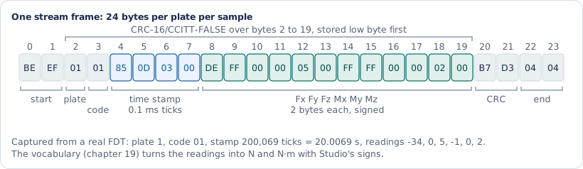
Table 2.1 Stream frame layout, firmware 1.2.8.0
| Bytes | Size | Code name | Type and wire order | Content | Evidence |
|---|---|---|---|---|---|
| 0-1 | 2 | header |
uint16 with value 0xEFBE, so BE EF on the wire |
Reply marker | vector |
| 2 | 1 | platform_address |
uint8 | Plate address. The value is 0 for a plate that has never answered | vector |
| 3 | 1 | commandCode |
uint8 | 0x01, the START code | vector |
| 4-7 | 4 | timeStamp |
uint32, little-endian | Plate stamp in 0.1 ms ticks (Section 5) | vector |
| 8-9 | 2 | forceX |
int16, little-endian | vector | |
| 10-11 | 2 | forceY |
int16, little-endian | vector | |
| 12-13 | 2 | forceZ |
int16, little-endian | vector | |
| 14-15 | 2 | momentX |
int16, little-endian | vector | |
| 16-17 | 2 | momentY |
int16, little-endian | vector | |
| 18-19 | 2 | momentZ |
int16, little-endian | vector | |
| 20-21 | 2 | crc |
uint16, little-endian | CRC over bytes 2 to 19 | vector |
| 22-23 | 2 | eot1, eot2 |
04 04 |
End marker | vector |
The struct is packed, so the offsets above are the wire offsets. The CRC is CRC-16/CCITT-FALSE over the 18 bytes from platform_address to momentZ. The variant and the wire rule are defined in 03-host-link-framing.md and are used here as given.
The layout is the one of 1.2.6.5. The frame did not change in 1.2.7.0 and 1.2.8.0. Those versions changed how the input readings are taken and how the frames are paced and stamped (Sections 3.1, 4 and 5).
Other clients use other names for the same fields. An earlier Python reference names the fields address, timestamp, force_x to moment_z. A phone client names them address, tick and a values array of six. The decoded field names in this chapter, and in the test vectors, are the firmware names in Table 2.1.
3. What the six integers are
Section titled “3. What the six integers are”3.1 The chain from pad reply to frame
Section titled “3.1 The chain from pad reply to frame”Evidence: code.
Each GET_FRAME reply of a pad carries eight int16 channels. From 1.2.7.0, a pad on queued samples answers GET_SAMPLES instead, with up to eight conversions of the six channels 0, 1, 2, 4, 5 and 6 (Section 4.8). The pad bus side of both replies is the controller’s internal pad bus and is not part of the host protocol.
The frame’s forces and moments are computed from one input reading per pad at each frame, in this order.
- The plate takes, for each pad on queued samples, the pad’s channels resampled to the frame’s grid time. For each other pad it takes the mean of the replies received since that plate’s previous frame (Section 4.8). A pad with no new data gives its held reading (Section 7.1).
- The tare of that pad and channel is subtracted in 32-bit arithmetic.
- Channels 1, 2, 4 and 5 change sign.
- The result is saturated to int16.
- The second-order Butterworth low-pass runs on the channel. Its output is rounded and saturated to int16 (Section 4.6).
- The channels are combined into forces and moments for the plate type (Table 3.1).
- Each force is multiplied by its plate factor and by 98, then divided by 100000. Each moment is then divided by 100. The factors are set to the factory defaults at start-up and are replaced by the saved values when the flash data is loaded. The commands 0x14 and 0x15 step a factor within the limits 1 and 200 (FACTOR_MAX).
- Each output is cast to int16 without saturation.
Only channels 0, 1, 2, 4, 5 and 6 enter the outputs. Channel 3 is filtered and unused. Channel 7 is filtered and unused as a reading. In pad firmware 2 and later it carries the pad health word.
For a pad on queued samples, channel 3 of the input holds the pad’s conversions per second and channel 7 its health word. Both come from its latest answer that carried a conversion, and neither is resampled.
Table 3.1 Channel use by plate type
| Output | Single plate | Double plate (pad 1 and pad 2 terms) |
|---|---|---|
forceX |
channel 6 times factorX |
channel 6 of pad 1 plus channel 6 of pad 2, times factorX |
forceY |
channel 0 times factorY |
channel 0 of both pads, times factorY |
forceZ |
channels 1, 2, 4 and 5 summed, times factorZ |
channels 1, 2, 4 and 5 of both pads summed, times factorZ |
momentX |
SENSOR_FZ_OFFSET_Y_SINGLE times (channel 5 + channel 4 - channel 1 - channel 2), times factorZ, divided by 100 |
the outer and inner terms of Fz, with SENSOR_FZ_OUTER_OFFSET_Y_DOUBLE and SENSOR_FZ_INNER_OFFSET_Y_DOUBLE, times factorZ, divided by 100 |
momentY |
SENSOR_FZ_OFFSET_X_SINGLE times (channel 5 + channel 1 - channel 4 - channel 2), times factorZ, divided by 100 |
the eight Fz terms of both pads with SENSOR_FZ_OFFSET_X_DOUBLE, times factorZ, divided by 100 |
momentZ |
SENSOR_FX_OFFSET_Y_SINGLE times channel 6, times factorX, divided by 100 |
(Fx of pad 1 minus Fx of pad 2) times SENSOR_FX_OFFSET_Y_DOUBLE, times factorX, divided by 100 |
The lever constants are integers fixed in the firmware. The code gives no physical meaning to them, and this chapter does not list their values.
Plate type is 1 for a single plate and 2 for a double plate. The number of pads in a plate is the plate type.
3.2 Output range
Section titled “3.2 Output range”Evidence: code.
The reading path saturates. The output casts do not. A force or moment outside the int16 range therefore wraps in the frame. The factor limit is 200, and the arithmetic of a double plate at that factor and full-scale readings exceeds int16 (open point 7). No capture shows a wrap.
3.3 Units
Section titled “3.3 Units”No source names a unit for the force or moment integers. The scaling constants 98 and 100000 have no comment in the code. An earlier Python reference states that its units remain unverified. This chapter assigns no unit and treats the integers as counts of the controller’s scaling (open point 8).
4. Rate, pacing and port selection (F3)
Section titled “4. Rate, pacing and port selection (F3)”4.1 The stream rate is the filter sample rate
Section titled “4.1 The stream rate is the filter sample rate”Evidence: code.
The stream rate for each plate is the filter sample rate rounded to an integer and clamped to 50 to 2000 frames per second. The filter sample rate defaults to 500 (1,000 from firmware 1.2.8.8). SET_FILTER replaces it, and the cutoff must stay below half of it. The GET_SAMPLING_RATE value is a stored number that does not drive the stream (Table 3.2 of 04-host-commands.md).
The filter runs once per outgoing host frame of the plate, which is 500 frames per second per plate at the default. SET_FILTER sets the stream rate as well as the filter. In every build except the synthetic build of Section 4.9, the main loop reads the rate on every pass. The frame rate follows the sps of SET_FILTER, up to 2,000.
4.2 Frames on one grid, and the backlog cap
Section titled “4.2 Frames on one grid, and the backlog cap”Evidence: code. Not run on hardware.
In the normal build of 1.2.8.0, which is every build except the synthetic build of Section 4.9, frame m of every plate is for TIM2 tick m times 10,000 divided by the rate, rounded to the nearest tick. All plates share one grid of frame times, paced by the crystal, not by the loop. The grid steps 20 ticks at 500 frames per second, 10 ticks at 1,000 and 5 ticks at 2,000. Each plate keeps the index and the tick of its next frame.
That frame falls due once its grid time lies at least the frame latency in the past, measured on the core’s cycle counter (Section 5.7). The latency is set in Section 4.8, and it is 0 while queued pad samples are off.
At the start of a stream, and after a change of rate, a plate’s next frame is the newest frame whose time lies at least the latency in the past, but never a frame at or before the plate’s last stamp.
When the next frame is late by two or more whole frame periods, its index moves forward by one less than that number of periods. A plate therefore has at most two frames due at once after a stall. The frames it moved past are never calculated or sent. Their grid times are missing from the plate’s stamps.
In 1.2.6.5 the normal build counted slots from timestamp instead. The synthetic build keeps that counter (Section 4.9).
4.3 Scheduling in the main loop
Section titled “4.3 Scheduling in the main loop”Evidence: code.
The main loop runs the pad polling and the frame sending once per pass. The frame sender reads the rate, prepares the resampling kernel for it, and visits the plates in turn, starting after the plate it visited last. It sends the first frame that is due and returns, so it sends at most one frame per pass. A code comment gives the reason as keeping the pace of the plate polling.
A plate that is not detected is skipped without a frame. When both plates are present the turn alternates between them, so the frames alternate, plate 1 then plate 2.
4.4 Pad polls and frames run on one loop
Section titled “4.4 Pad polls and frames run on one loop”Evidence: code, and one bench figure (measured, earlier builds).
Pad polls are issued in the same loop. A pad on GET_FRAME is polled as before 1.2.7.0. After a GET_FRAME poll the next poll falls due 700 microseconds later, because the gap and the minimum after an answer are both set to that value.
Each frame of such a pad’s plate uses the replies from that pad received since the plate’s previous frame. A reply whose readings are all zero is not accumulated, and neither is any reply after a pad’s count reaches 65,535.
A code comment gives about 320 new samples per second per pad, and a bench record gives the same figure. That is less than the 500 frames per second per plate, so some frames carry no new reply from a given GET_FRAME pad and take the stale path (Section 7.1).
A pad on queued samples is polled as Section 4.8 describes and gives a reading at each frame’s own time. The share of stale frames on 1.2.8.0 was not measured (open point 3).
4.5 The stream goes to the port of the last valid command
Section titled “4.5 The stream goes to the port of the last valid command”Evidence: code, and a host test in software.
Stream frames are transmitted on the active port. An accepted command sets that port to the port it arrived on, and the port stays selected until the next accepted command. A request that latches nothing restores the previous port. The stream therefore moves to whichever host port last sent a valid command.
The host test repeats a stream frame on the USB port after a USB command. A second host that sends any valid query while another host streams takes the stream (open point 10).
4.6 The filter runs once per calculated frame
Section titled “4.6 The filter runs once per calculated frame”Evidence: code.
The filter state for each plate, pad and channel advances once per calculated frame. A frame is calculated before it is sent, so a frame that the TX ring then drops has still advanced the filter. A grid frame skipped after a stall is never calculated. The filter’s time base is therefore frames, not timer ticks. The size of the effect after a stall was not measured (open point 4).
4.7 F3, stated and checked
Section titled “4.7 F3, stated and checked”F3 is the claim that the stream carries one frame per due slot at the filter sample rate for each plate, that it never sends more than two frames behind schedule, that a stale plate repeats its held reading, and that a full TX ring drops frames with no retry.
The 1.2.8.0 code supports each part, with the grid times of Section 4.2 as the due slots (code). The stream does not report a drop or a stale frame to the host (Section 8). The grid pacing has not been run on hardware (open point 13).
4.8 Queued pad samples and the frame latency (1.2.7.0 and 1.2.8.0)
Section titled “4.8 Queued pad samples and the frame latency (1.2.7.0 and 1.2.8.0)”Evidence: code and simulation. Not run on hardware.
While the stream runs, a pad whose health word reports pad firmware code 11 or later is polled with the pad command GET_SAMPLES instead of GET_FRAME. Code 11 is pad application 2.8. The pad must also be running normally, with no reset wanted and a count of polls missed in a row below three. The pad-sample debug command 0x63 must not have turned the mode off.
A poll counts as missed only when the next poll of that pad is sent. A pad that stops answering therefore gets four GET_SAMPLES polls without an answer, and the fifth poll is GET_FRAME.
Each answer carries the conversions since the pad’s previous answer, up to eight. The controller polls the next pad as soon as an answer is in, plus a 50 microsecond guard, or after 900 microseconds without an answer. It polls the same pad at most once per millisecond.
For each frame, the six measured channels of such a pad are resampled to the frame’s grid time from the pad’s conversions around it, with a windowed-sinc kernel built for the frame rate. The kernel uses 16 conversions from 743 frames per second up, 24 from 372, and 32 below, at the default 1,953.125 conversions per second. It is rebuilt in the main loop when the frame rate or the ADC clock divider changes, and the boot code builds it for the boot rate.
A frame waits until the last conversion that its kernel needs can have arrived. The wait is half the kernel length in conversion periods, plus 2.5 periods for the delay that the code assigns to each conversion’s value, plus 5 milliseconds of margin. A code comment gives 10.4 ms from 743 frames per second up, 12.4 ms from 372, and 14.5 ms below. That is the same arithmetic with one conversion every 512 microseconds.
At 500 frames per second (the default up to firmware 1.2.8.7; 1.2.8.8 and later default to 1,000) a frame therefore leaves the device about 12.4 ms after its grid time. The wait applies to every plate while the mode is on, including a plate whose pads are all on GET_FRAME. After START, the first frame of each plate is frame 1, which falls due one grid step plus the latency after the stream starts.
The pad-sample debug command 0x63 with parameter 0 turns queued samples off in RAM. Every pad is then polled with GET_FRAME, and the latency is 0. Parameter 1 turns them on again, which is the state after a reset. The command is a bench command and must not be sent (Table 3.5 of 04-host-commands.md). A plate stays stamped on the grid until the stream stops, even after its pads leave queued samples (Section 5.2).
The grid pacing, the queued samples and the frame latency have not been run on hardware, and they are unverified on a device (open point 13). Controller 1.2.7.0 and 1.2.8.0 and pad application 2.8.0.0 were merged with simulation tests only. The host tests run the shared queue and resampler code on a model of the bus, and they model the frame grid in the test’s own code. The test script compiles none of the controller’s pacing, timer and calculation code.
4.9 The synthetic build
Section titled “4.9 The synthetic build”Evidence: code.
A build with a build-time synthetic frame rate is a transport test. This chapter calls every other build the normal build, whatever its signing key. The synthetic build reports the version 1.2.8.0-SYN. It sets both plates to single plates at boot, polls no pad during a stream, and calls the frame sender eight times per pass. Its rate is the build-time rate, with the lower clamp only.
It paces frames with the slot counter of 1.2.6.5. The slots due are timestamp times the rate times the number of detected plates, divided by 10000. A frame is due while the frames sent are fewer than the slots, and the count is moved up so that at most two frames are owed.
A code comment gives the reason for pacing: free-running, the rate depended on loop timing, at about 626 frames per second per plate, which shifted the filter cutoff and overran the BLE bridge. Its frames carry counters, not measurements. Each stamp is the frame count times 10000 divided by the rate times the number of detected plates.
4.10 Analog outputs
Section titled “4.10 Analog outputs”Evidence: code.
When the normal build calculates a frame, it also updates that plate’s analog outputs, but only on every n-th frame. Here n is the stream rate divided by 500 (DAC_UPDATE_MAX_HZ), rounded up. At 500 frames per second and below every frame updates the outputs, and at 1,000 every second frame does.
A code comment gives the reason: eight SPI writes cost about 0.1 ms, which at 1,000 frames per second and more would hold up the plate polling. The update writes nothing while ANALOG_ENABLE has the outputs off. The count restarts with each stream.
The outputs are written when the frame is calculated, so with queued samples they lag the signal by the latency of Section 4.8. This compares with 4 to 5 ms in 1.2.6 (a design estimate, not measured here). See 23-analog-outputs.md.
5. Stamps
Section titled “5. Stamps”5.1 The timer
Section titled “5.1 The timer”Evidence: code.
Timer interrupt TIM2 adds one to timestamp on each update while the stream runs, and sets it to zero otherwise. The timer is set with a prescaler of 83 and a period of 99. With a TIM2 clock of 84 MHz, that is 10 kHz, so one tick is 0.1 ms. The 84 MHz timer clock was not measured (open point 1).
The earlier Python reference uses the same tick. Its comment says a source-derived device tick is 100 microseconds, and its capture summary records the same value as an inferred assumption.
5.2 The plate stamp
Section titled “5.2 The plate stamp”Evidence: code. Not run on hardware.
From 1.2.8.0 the stamp of a release-build frame depends on how the plate’s pads are polled.
- A plate is on the grid once any of its pads is on queued samples when one of its frames is built, and it stays on the grid until the stream stops. Its stamp is the grid tick of the frame. The readings of a pad on queued samples are resampled to that time (Section 4.8), so the stamp is the time that the data describe. At 500 frames per second the stamps are 20, 40, 60 and so on, and two plates on the grid carry the same stamps.
- Any other plate is stamped as before 1.2.8.0. The plate stamp is the mean of the per-pad mean ticks of the pads that answered, truncated to an integer. The per-pad mean tick is the rounded mean of the timer values stored when each reply was parsed. When no pad of the plate answered since the previous frame, the stamp is the timer value at the moment the frame is built.
Either way the stamp lies on the same 0.1 ms timeline as the timer. It is not the send time, except for a stale frame of a plate off the grid, which is stamped when it is built. A frame is sent at least the latency of Section 4.8 after its grid time. The synthetic build stamps its frames from the frame count instead (Section 4.9).
5.3 Monotonic rule
Section titled “5.3 Monotonic rule”Evidence: code.
For each plate, a stamp that is not greater than the previous frame’s stamp is replaced by that stamp plus one. The rule is not applied to the first frame after a start, because the previous stamp is zero then. Within a stream, the stamps of one plate are strictly increasing.
The rule applies to grid stamps and to stamps from reply ticks alike. Grid stamps of one plate rise by one grid step per frame, or by more after skipped frames (Section 4.2). The stamps of the two plates are not ordered with each other, except that two plates on the grid carry the same stamp for the same frame index.
5.4 Receipt tick and poll tick
Section titled “5.4 Receipt tick and poll tick”Evidence: code and simulation.
For a plate stamped from reply ticks (Section 5.2), the code stores the timer value at receipt, after the reply has been parsed. Two code comments say that such a stamp is the poll time. A third comment calls it the mean time of the pad replies used. The difference between poll and receipt is the reply latency, which the code does not measure (open point 6).
For a plate on the grid the stamp is the frame’s own time, and the conversions around it are placed in time from the pads’ answer timing. A simulation puts every such stamp about 40 microseconds late and the pads up to about 50 microseconds apart while the estimate settles. That is a model with estimated pad latencies, not a measurement (open point 14).
5.5 Restart and wrap
Section titled “5.5 Restart and wrap”Evidence: code.
The timer is zero while the stream is off, and the per-plate stamp and grid state is cleared when the stream stops. Each START after a STOP therefore starts again near zero. A host must treat the start of each stream as a new segment. The stamps alone do not show the break, because the new stream’s stamps can pass the old last stamp.
The stamp is 32 bits. The counter wraps after 2^32 ticks, which is 429,496.7296 seconds.
5.6 Host unwrap
Section titled “5.6 Host unwrap”Evidence: code (the reference decoders).
The reference decoders classify each stamp against the previous stamp of the same plate.
- A repeat is
duplicate_timestamp. - A backward step larger than 2^31 is
wrap, which adds 2^32 to the unwrapped value. - Any other backward step is
reset_or_out_of_order, and it starts a new segment. - A forward step is
forward.
A nine-frame synthetic example records the expected labels (Section 10.4).
5.7 Grid time and the cycle counter
Section titled “5.7 Grid time and the cycle counter”Evidence: code.
The grid of Section 4.2 is kept on the core’s cycle counter, which the boot code enables. On each TIM2 tick, the interrupt records the cycle count and keeps the earliest back-projection of tick 0 of the stream. A code comment gives the ground: TIM2 counts the core clock, so tick k is at tick 0 plus k times 8,400 cycles, and interrupt latency only makes a tick look later.
The conversion from a tick to a cycle count is limited to ticks within about 25 seconds of now. The conversion back gives the tick of a recent cycle count, never less than 1. A comment says that the cycle counter wraps after 51 seconds at 84 MHz. The grid code converts only times near the current time.
The 8,400 cycles per tick hold only for the 84 MHz clock of open point 1, and no host test compiles the timer code (open point 13).
6. Start-up placeholders
Section titled “6. Start-up placeholders”6.1 What START sends
Section titled “6.1 What START sends”Evidence: code.
From 1.2.6.6, START first runs the platform redetection. When a plate is missing, it sweeps for it again and, within the first 8 seconds of uptime, waits for it. It then tares any detected plate that has never been tared. The details are in Section 3.8 of 04-host-commands.md.
START then sends two frames before the stream flag is set. Each has timeStamp 0 and one of the platform addresses 1 and 2, whether or not that plate was detected. Each frame’s platform_address, forces and moments are copied from the platform structure at the time the frame is sent. The placeholder for a plate that has never answered therefore has platform_address 0. Its force and moment fields hold whatever the structure last held.
START sends no ACK, so these frames are the only sign that START worked (F2).
6.2 What a capture shows
Section titled “6.2 What a capture shows”Evidence: measured, on a capture of an earlier firmware. The capture is not included in vectors/.
The capture’s first two frames are these placeholders: index 0 is plate 1 and index 1 is plate 2, each with stamp 0 (Section 10.1, S1 and S2). They are the only frames with stamp 0 in the 19,057-frame capture. The forces in them are small non-zero values, which the code does not reset at START.
6.3 Placeholders in the middle of a stream
Section titled “6.3 Placeholders in the middle of a stream”Evidence: code.
START is accepted while a stream runs, except during a firmware update. A START during a stream sends the two zero-stamp placeholders again. It does not reset the timer, the grid or the stamp state, which are reset only while the stream is off. It clears the pad means and drops the queued conversions.
It also runs the platform redetection, so a START during a stream with a plate missing or never tared pauses the stream while it sweeps or tares (Section 6.1, Section 7.4). A host therefore sees zero-stamp frames after measured frames on the same timeline. Whether the SDK sends START while a stream runs is not settled, and the clients do not do it.
6.4 Host rule
Section titled “6.4 Host rule”A zero stamp is a placeholder wherever it occurs. It is not a measurement, and it marks a segment break for the unwrap in Section 5.6. A decoder that marks only the zero stamps before the first non-zero stamp of a plate as unmeasured would report a zero stamp after a measured frame as a measurement with a new segment. Do not do that.
7. Stale frames, drops and stalls
Section titled “7. Stale frames, drops and stalls”7.1 Stale frames
Section titled “7.1 Stale frames”Evidence: code.
When no pad of a plate has new data for a frame, the plate’s frame takes the held reading of each pad.
- A pad on GET_FRAME has no new data when no reply arrived since the plate’s previous frame. The controller then returns the pad’s latest reading.
- A pad on queued samples has no new data when the resampler finds no conversion near the frame’s time. Its readings then stay the newest ones received.
- A value that the resampler fills from some of the conversions counts as new data.
The forces are still calculated from the held readings, and the plate’s stale counter is incremented. The stamp of a stale frame is the grid tick for a plate on the grid, and otherwise the timer value when the frame is built (Section 5.2). The counter is reported per plate in GET_PAD_HEALTH.
The held reading passes through the filter as a new input. A stale frame’s forces are therefore the filter’s next output for the held input. They are not a copy of the previous frame’s forces. The frame carries no mark that it is stale (Section 8).
A pad counts as not answering when its last reply is more than 50 milliseconds old while the stream runs. That is a health flag, described in 06-status-health-versions.md.
7.2 Zero replies
Section titled “7.2 Zero replies”Evidence: code.
A reply whose eight channels are all zero is not added to the mean. It does overwrite the held reading of that pad. A frame that finds no non-zero reply since the previous frame therefore uses the zeros as its input.
A booting pad answers with zeros for about 1.7 seconds. A pad on queued samples that restarts stops answering GET_SAMPLES. After four polls in a row without an answer it is polled with GET_FRAME again, so its zero replies take this path too (Section 4.8). The frames sent during that time were not observed (open point 5).
7.3 Drops at the TX ring
Section titled “7.3 Drops at the TX ring”Evidence: code.
A stream frame that finds the 4096-byte TX ring full is dropped at once. The drop is counted, but no reply reports the counter. A host sees a drop only as a gap in the plate’s stamps. The frequency of drops was not measured (open point 11).
7.4 Stalls and gaps
Section titled “7.4 Stalls and gaps”Evidence: code. Not run on hardware.
No frame is built while the main loop is busy with another command. After such a stall, the stamps jump across the stall, and at most two owed frames are sent (Section 4.2).
SET_TARE is a blocking command, and the stream pauses for its duration. The code says so: “the stream simply pauses for its ~0.3-4 s while the stream clock keeps running; frames resume with later stamps”.
The tare also clears the filter state, so the first frames after it carry a settling transient (open point 9). It drops the queued conversions as well, so the first grid frames after it can find no conversion near their time and become stale frames (Section 7.1). How many frames that affects was not measured.
7.5 SET_FILTER during a stream
Section titled “7.5 SET_FILTER during a stream”Evidence: code. Not run on hardware.
SET_FILTER is not refused while a stream runs. The new rate applies at the next pass, because the frame sender reads the rate on every pass.
When the rate differs from the rate of the grid, every plate restarts on the grid of the new rate. Its next frame is the newest frame of the new grid whose time lies at least the latency in the past, and never a frame at or before the plate’s last stamp.
The resampling kernel and the latency are rebuilt for the new rate in the same pass. A code comment puts that at a few milliseconds of float work. A change of rate therefore leaves a gap in the stamps of up to about one frame period, plus the rebuild time, plus any fall of the latency. The planned bench test expects no gap beyond a few frames, and it has not been run (open point 13).
In 1.2.6.5 a lower rate left no frame due until the slot count caught up with the frames already sent. A change from 500 to 250 frames per second ten minutes into a stream gave ten minutes with no frames. Only the synthetic build keeps that counter (Section 4.9).
Only a cutoff of 0 resets the filter state: it turns the filter into a bypass, and entering bypass resets the filter. A nonzero cutoff changes the coefficients without a reset, so a filter that leaves bypass starts from the zero state that the bypass left (open point 9). The frame has no field that marks either change (Section 8).
7.6 STOP
Section titled “7.6 STOP”Evidence: code.
STOP sends its ACK before it clears the stream flag. A frame built after the flag clears is not possible, because the frame loop runs only while the flag is set. Frames already queued on the same port are ahead of the ACK in the ring.
A host that waits for the STOP ACK has therefore received every frame that was queued on that port before the ACK. A frame that found the TX ring full was dropped and never queued, so the host did not receive it (Section 7.3). The ACK itself is dropped if the ring stayed full for 50 milliseconds.
With queued samples on, the frames whose grid times lie within the latency before STOP are not yet due when the flag clears, and they are never sent (Section 4.8).
8. What the stream does not carry
Section titled “8. What the stream does not carry”Table 8.1 Information that is not in the 24-byte frame
| Information | In the stream | Where it is instead |
|---|---|---|
| Quality or validity flag | No field | Error bits in GET_STATUS and flags in GET_PAD_HEALTH |
| Stale-frame mark | No | Cumulative counter per plate in GET_PAD_HEALTH |
| Sequence number | No | Stamp only |
| Number of replies averaged into a frame | No | Counted in the pad link state for a pad on GET_FRAME. For a pad on queued samples the resampler counts exact, filled and missing values, and no reply reports those counters |
| Pad identity inside a plate | No, only the plate mean | The per-pad readings are not sent |
| Raw pad channels | No, only forces and moments | Not sent by any command |
| Channels 3 and 7 | No | Not used by the outputs (Section 3.1) |
| Epoch or wrap count | No, 32 bits only | Host unwrap (Section 5.6) |
| Count of dropped frames | No | Counter exists and is not reported |
| Physical unit | No | Not defined (Section 3.3) |
| Plate type and pad count | No | GET_CURRENT_CONFIG |
The quality question has one answer. The 24-byte frame has no quality field, and no value in the frame marks a sample as stale, placeholder or unanswered. The only quality sources are the status records and the 120-byte GET_PAD_HEALTH reply, described in 06-status-health-versions.md.
9. Decoding a byte stream
Section titled “9. Decoding a byte stream”9.1 Procedure
Section titled “9.1 Procedure”Evidence: code (the reference decoders).
- Buffer the bytes as they arrive. Do not cut the buffer on
04 04(Section 9.2). - Search for
BE EF. Discard the bytes before it. If the buffer ends inBE, keep that byte, because the next read can complete the header. - Read
commandCodeat offset 3. For 0x01 the frame is 24 bytes. - Wait for 24 bytes. Check that bytes 22 and 23 are
04 04, and that the CRC at bytes 20 and 21 equals the CRC over bytes 2 to 19. - If the check fails, count a rejected candidate, discard one byte and search again.
- If the check passes, take the plate from byte 2. The phone client accepts 1 and 2 and reports any other value as an anomaly. Take the stamp from bytes 4 to 7 and the six integers from bytes 8 to 19.
- Classify the stamp as in Section 5.6, and mark zero stamps as placeholders as in Section 6.4.
9.2 Splitter hazard
Section titled “9.2 Splitter hazard”Evidence: code, and a capture census (measured).
The device’s own receive splitter ends a message at the first two consecutive 04 bytes. A stream frame whose CRC high byte is 04 has 04 04 at bytes 21 and 22, because byte 22 is eot1. A splitter that uses that rule ends the message after byte 22. The final 04 at byte 23 then starts the next message, which carries it as a stray first byte. The framing rule for CRC bytes is in 03-host-link-framing.md.
In the capture of Section 10.2, 82 of the 19,057 frames have this CRC high byte. Only one frame has a 04 04 pair inside bytes 0 to 21: capture index 16298, at offset 391152, has CRC 0x0404, so its pair is at bytes 20 and 21. The rule ends that message after byte 21, so bytes 0 to 21 form one message, and the end marker at bytes 22 and 23 forms a two-byte message of its own. The frame is therefore not delivered whole.
Frame 169 (capture index 169, offset 4056) is one example of the CRC-high-byte case, and Table 10.1 does not list it.
A parser that takes the length from the command byte and checks the CRC does not split on the pair, and it is not affected.
10. Worked frames and the capture
Section titled “10. Worked frames and the capture”10.1 Worked frames
Section titled “10.1 Worked frames”Table 10.1 Decoded stream frames
| Frame | Source | Wire bytes | platform_address |
timeStamp |
forces X, Y, Z | moments X, Y, Z | crc on the wire |
Evidence |
|---|---|---|---|---|---|---|---|---|
| S1 | capture index 0, offset 0 | beef010100000000f9ff06000700000000000000189e0404 |
1 | 0 | -7, 6, 7 | 0, 0, 0 | 18 9E, 0x9E18 |
vector |
| S2 | capture index 1, offset 24 | beef020100000000f9ff12000f00feffffff000063760404 |
2 | 0 | -7, 18, 15 | -2, -1, 0 | 63 76, 0x7663 |
vector |
| S4 | capture index 19,056, offset 457344 | beef0101850d0300deff00000500ffff00000200b7d30404 |
1 | 200069 | -34, 0, 5 | -1, 0, 2 | B7 D3, 0xD3B7 |
vector |
| Test frame | the controller’s transport test, computed | beef010140e2010085ff0000c801000000000000064c0404 |
1 | 123456 | -123, 0, 456 | 0, 0, 0 | 06 4C, 0x4C06 |
code |
The capture is a recording from an earlier firmware. It is 457,368 bytes, with no CRC failures, and it is not included in vectors/. The Test frame is the frame that the controller’s transport test builds for platform 1 with platform_address 1, forceX -123, forceZ 456 and timeStamp 123456. The struct is zero-initialised, so forceY and the moments are 0. The test asserts the length and the CRC only.
Twelve decoded records were prepared for conformance. Three are stream frames (S1, S2 and S4). The other nine are replies from identification captures. The nine replies were not decoded again for this edition (open point 12).
10.2 Capture census
Section titled “10.2 Capture census”Evidence: measured, on a recording from an earlier firmware.
Table 10.2 Census of the capture
| Measure | Value |
|---|---|
| Length | 457,368 bytes, which is 19,057 frames of 24 bytes |
| Header, command, end marker | BE EF, 0x01 and 04 04 in every frame |
| CRC failures | 0 |
| Plate 1 frames | 9,529, of which 9,528 are steady |
| Plate 2 frames | 9,528, of which 9,527 are steady |
| Zero stamps | 2, at indexes 0 and 1 |
| Plate alternation | Strict: plate 1 at even indexes, plate 2 at odd indexes |
| Steps between steady frames, plate 1 | 9,527, all 21 ticks |
| Steps between steady frames, plate 2 | 9,525 of 21 ticks, one of 22 ticks at index 17,543 |
| First step after the placeholder | 2 ticks for plate 1 (index 2), 12 ticks for plate 2 (index 3) |
Frames with CRC high byte 04 |
82 (Section 9.2) |
| Gaps of two or more slots | None: no step other than 21 or 22 in steady frames |
| Plate 1 span | Stamp 0 to 200,069 ticks, which is 20.0069 seconds |
| Wall duration and rates | 20.0106893 seconds; 476.2 frames per second per plate; 952.3 frames per second in total |
The step of 21 ticks is 2.1 ms, which gives 476.2 frames per second per plate. The 1.2.8.0 grid gives 500 frames per second per plate, which is one frame every 20 ticks for each plate, and two plates on the grid carry the same stamps (Sections 4.1, 4.2 and 5.2).
The capture’s two plates do not share stamps: their first stamps after the placeholders are 2 and 12 ticks. The capture’s firmware is not identified here, and the cadence difference is an open point (point 2). The earlier reference notes record the observed delivery of about 476 frames per second per platform.
10.3 Which build produced the capture
Section titled “10.3 Which build produced the capture”The earlier reference labels the observed behaviour with a profile name and states that the label does not attest the deployed firmware build. The capture obeys the 24-byte layout in Table 2.1 in every frame. The build that produced it is not identified, and it is open. Only the layout is shared with 1.2.8.0.
10.4 Timestamp example
Section titled “10.4 Timestamp example”Evidence: code (a client test).
A nine-frame synthetic example (216 bytes) records the expected labels of Section 5.6. It holds 9 messages, 9 samples, 0 invalid candidates and 0 discarded bytes. The labels are:
initial: plate 1 and plate 2 at stamp 0.forward: plate 1 at 20, plate 2 at 21.duplicate_timestamp: plate 1 at 20 again.forward: plate 1 at 4294967294.wrap: plate 1 at 3, unwrapped to 4294967299.reset_or_out_of_order: plate 2 at 19, a new segment.forward: plate 2 at 20 in segment 1.
The values are synthetic. Frame 6 has CRC high byte 04, which is the splitter case of Section 9.2.
11. Open points
Section titled “11. Open points”All of these are unverified on a device.
- The stamp unit of 0.1 ms needs TIM2 to run at 84 MHz. The prescaler, the period and the PLL and APB1 settings give that rate only under the vendor’s timer-clock rule. The rate was not measured. (Code and vendor rule.)
- The capture steps 21 ticks (476 frames per second per plate). The 1.2.8.0 grid gives one frame per 20 ticks for each plate. A plate on the grid is stamped with the grid tick, and any other plate with reply ticks, so only the first has its step fixed by the grid (Section 5.2). The build that made the capture is not identified.
- The share of stale frames on 1.2.8.0. With pads on GET_FRAME it depends on pad replies of about 320 samples per second per pad against 500 frames per second per plate (Section 4.4). With pads on queued samples a simulation has no frame without a conversion except for a restarting pad. There is no capture of 1.2.8.0.
- The size of the filter’s time-base change after a stall, when skipped grid frames are not calculated (Section 4.6).
- The values of frames sent while a pad answers zeros during a cold boot (Section 7.2), because a zero reply overwrites the held reading.
- The reply latency between the poll and the receipt tick used as the stamp of a plate stamped from reply ticks (Section 5.4). A bench record gives 250 to 300 microseconds to answer, from earlier builds (measured, not repeated on 1.2.8.0).
- A wrap of a force or moment at the output cast (Section 3.2) at full-scale readings and factor 200. The arithmetic admits it for a double plate. No capture shows one.
- The physical unit of each integer, and the meaning of the constants 98 and 100000 in the scaling (Section 3.3).
- The length of the filter transient after SET_TARE, which clears the state, and after SET_FILTER. Only a cutoff of 0 clears the state. A nonzero cutoff does not, so leaving bypass starts from zero state (Sections 7.4 and 7.5).
- Stream routing between two host ports, and the effect of a valid command on the other port (Section 4.5). The host test covers it in software only.
- How often the TX ring drops a stream frame under a host that reads slowly (Section 7.3).
- The nine reply records among the twelve conformance records (Section 10.1) were not decoded again. The three stream records and the capture census were recomputed.
- The grid pacing, the grid stamps, the queued pad samples, the resampler and the frame latency of 1.2.7.0 and 1.2.8.0 (Sections 4.2, 4.3, 4.8, 5.2, 5.7, 7.4, 7.5 and 7.6), including the frames around a change of the pad-sample debug command during a stream. The code was merged with simulation tests only.
- The offset between a grid stamp and the time its readings describe. A simulation puts every stamp about 40 microseconds late, with the pads up to about 50 microseconds apart while the estimate settles and about 11 microseconds apart after a few seconds. The pad latencies in that model are estimates (Section 5.4).
12. Known inconsistencies
Section titled “12. Known inconsistencies”- Firmware comments describe a stamp formed from pad replies as the poll time. Such a stamp is the mean of the timer values at parse time. A plate on the grid is stamped with its frame time instead (Section 5.4).
- A stale frame’s forces are the filter’s next output for the held input, not a copy of the previous frame (Section 7.1).
13. Event frames (FDT 1.2.8.24, draft)
Section titled “13. Event frames (FDT 1.2.8.24, draft)”Evidence: code of the 1.2.8.24 draft and its vectors. Not yet run on hardware.
One change in 1.2.8.24 reaches every host: the six outputs are clipped at the int16 limit instead of wrapping around at the conversion of Section 3.2 (a decision of 28 October 2026). Event frames exist only when a host sets SET_SYNC_MODE 0x28 with bit 0x08 EVENT_FRAMES or 0x20 SATURATION_EVENTS (04-host-commands.md, section 3.9). A host that never sends 0x28, Movetrics Studio among them, receives exactly the stream of 1.2.8.22.
13.1 Why a separate frame
Section titled “13.1 Why a separate frame”A lab aligns the plates with EMG, cameras and a second FDT through edges on the sync jack. Three problems need three answers: where the recordings start relative to each other (a shared edge), how fast two crystals drift apart (typically 20 to 50 ppm, so 18 ms or 36 samples at 2000 Hz after 10 minutes at 30 ppm; inferred from crystal tolerances, not measured on the FDT), and gaps in the stream. An edge carried in its own frame gives its time to the microsecond instead of to the frame, costs nothing while no edge happens, and leaves the 24-byte measurement frame untouched. Its stamp is in the plate frames’ 0.1 ms time base, so alignment survives lost frames: the stamp is the time, not the frame count.
13.2 Layout
Section titled “13.2 Layout”Table 13.1 Event frame, 24 bytes
| Bytes | Field | Type | Content |
|---|---|---|---|
| 0-1 | header | BE EF |
as a stream frame |
| 2 | address | uint8 | 0xFD: the controller, no plate. A decoder that reads byte 2 as a plate number must skip it; Movetrics Studio logs an unknown platform and ignores the frame |
| 3 | code | uint8 | 0x0E STREAM_EVENT |
| 4-7 | stamp | uint32 LE | 0.1 ms tick of this stream at the event (nearest tick) |
| 8 | type | uint8 | Table 13.2 |
| 9 | source | uint8 | 0 for SYNC IN 1 and SYNC OUT 1 (the only jack lines the firmware knows); the plate address for saturation |
| 10-13 | counter | uint32 LE | per type, Table 13.2; a gap in it means event frames were lost |
| 14-15 | offset | int16 LE | microseconds from the stamp’s tick to the edge (within plus or minus 50 us; earlier for the edge that started the stream) |
| 16-17 | detail | uint16 LE | per type |
| 18 | mode | uint8 | the mode bits in force |
| 19 | reserved | uint8 | 0 |
| 20-21 | crc | uint16 LE | CRC-16/CCITT-FALSE over bytes 2 to 19, as a stream frame |
| 22-23 | end | 04 04 |
Edge time in seconds = (stamp x 100 + offset) / 1,000,000, in the same clock as every plate frame’s stamp.
Table 13.2 Event types
| Type | Name | Counter | Detail | Sent when |
|---|---|---|---|---|
| 1 | SYNC_IN_RISE | accepted SYNC IN edges since boot | 0 | EVENT_FRAMES, stream running |
| 2 | SYNC_IN_FALL | as 1 | 0 | as 1 |
| 3 | SYNC_OUT_RISE | SYNC OUT edges the FDT drove since boot | 0 | EVENT_FRAMES and MASTER_OUT or PULSE_TRAIN, stream running |
| 4 | SYNC_OUT_FALL | as 3 | 0 | as 3 |
| 5 | ARMED | SYNC IN edges so far | arm timeout, minutes | EVENT_FRAMES, START in START_ON_RISE mode; stamp 0 |
| 6 | TRIGGER_START | the counter of the edge that started the stream | 0 | EVENT_FRAMES, after that edge’s type 1 frame; same stamp and offset |
| 7 | SATURATION | episodes on this plate in this stream | channels out of range now: bits 0-5 fx fy fz mx my mz beyond int16 (the frame carries the clipped limit), bit 6 a pad channel clipped | SATURATION_EVENTS, first frame of an episode |
| 8 | DROPPED | frames lost in this stream | frames lost since the last report, capped at 65,535 | EVENT_FRAMES, at most every 100 ms, when the transmit ring dropped a frame or the grid skipped frames after a stall (Section 7) |
| 9 | SATURATION_END | as 7 | every bit seen during the episode | SATURATION_EVENTS, after 20 frames in a row without a bit |
| 10 | ARM_EXPIRED | SYNC IN edges so far | arm timeout, minutes | EVENT_FRAMES, the arm timed out without an edge; stamp 0 |
13.3 Ordering and loss
Section titled “13.3 Ordering and loss”Plate frames leave about 10 to 15 ms after their stamp (the resampler’s latency, Section 4.8); event frames leave within one main-loop pass of the edge. So an event frame usually arrives before the plate frames of the same moment. A host sorts by stamp, never by arrival. Event frames go through the same transmit ring as plate frames and are dropped, not waited for, when it is full; the counters show the gap, and type 8 reports it. Interrupts queue up to 32 events between two main-loop passes; GET_SYNC_MODE reports overflows.
13.4 Timing claims and how they are made
Section titled “13.4 Timing claims and how they are made”All inferred from code, none measured yet. An edge is timed by the cycle counter at the start of its interrupt, so its error is the interrupt latency, a few microseconds while another priority-0 interrupt runs. A pulse edge is late by the timer interrupt’s latency, which its offset reports. The trigger start puts tick 0 within one tick (0.1 ms) before the edge. A host that needs better than 0.1 ms uses the offset field, not the stamp alone.
13.5 Vectors
Section titled “13.5 Vectors”python/tests/fixtures/sync_events.json holds event frames of every type and two GET_SYNC_MODE replies, written by the firmware’s own encoder. The Python, TypeScript and MATLAB clients decode every case in their tests.